

Blog
What Is a Vertical Pair Twisting Machine?
A Vertical Pair Twisting Machine is built for controlled twisting of two yarns into one stable, balanced structure. It resembles a compact steel tower, with paired yarn paths, tension devices, spindles, and take-up units working in sequence. The machine matters where strength, uniformity, and production speed must coexist.
The International Textile Machinery Federation reported major movement in 2023 shipments. Short-staple spindles declined by 5.4%, while open-end rotors increased by about 21%. Draw-texturing spindle shipments also grew by approximately 12%. These figures do not isolate pair-twisting equipment. That limitation deserves attention. Still, they show an industry investing selectively in automation, flexibility, and yarn performance.
Textile machinery researcher Dr. J. Hayavadana explains the core principle clearly: “Twisting gives yarn strength, stability, and a distinctive appearance.” A Vertical Pair Twisting Machine applies that principle with tighter process control. Operators can monitor yarn tension, twist level, winding shape, and package density. Small deviations become visible quickly. That is useful.
According to Grand View Research, the global textile machinery market continues to expand through automation and advanced manufacturing demand. Energy consumption, maintenance access, and operator training remain practical purchasing concerns. A machine can appear efficient on paper, yet perform poorly with unstable yarn input. This is where real production experience matters.
The best evaluation should compare output consistency, twist accuracy, downtime, waste, and service support. Not merely speed. Buyers should test the machine with their actual yarn types before making a final decision. That step is often overlooked. Perhaps it should not be.
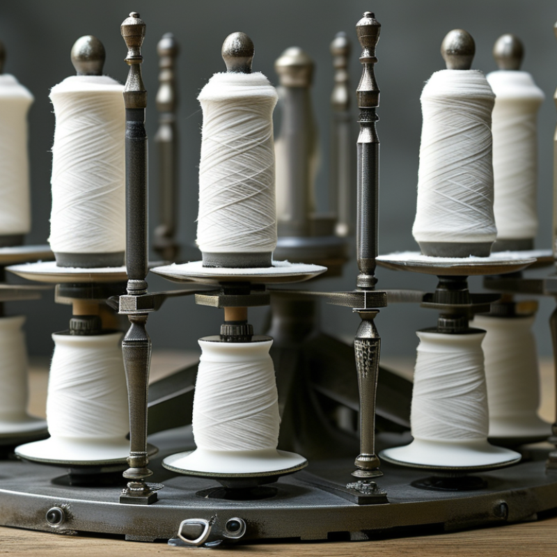
Definition and Core Function of a Vertical Pair Twisting Machine
What Is a Vertical Pair Twisting Machine?
A vertical pair twisting machine is industrial equipment designed to twist two yarns, wires, or narrow strands together. Its core function is simple: it combines separate materials into one stable twisted pair. The vertical structure guides the strands upward or downward through tension devices, twisting units, and a winding section.
During operation, each strand passes through an individual guide. The machine controls their tension before they meet at the twisting point. A rotating spindle then applies a measured number of twists. The finished pair is wound onto a package for later processing. This arrangement can improve handling, reduce strand separation, and create a more consistent product.
Practical performance depends on accurate setup. Operators usually check spindle speed, winding tension, guide alignment, and package shape. Even a small alignment error may cause uneven twisting or surface damage. Material differences matter too. A soft yarn may need gentler tension, while a rigid wire can require stronger guiding pressure. These adjustments are not always perfect on the first attempt. Experienced technicians inspect the first package closely and correct the settings before longer production runs. Regular cleaning also protects the guides and reduces unpredictable tension changes. The machine’s vertical layout can save floor space, although access may feel less convenient during maintenance. That trade-off deserves attention.
Main Components and Their Roles
What Is a Vertical Pair Twisting Machine?
A vertical pair twisting machine combines two insulated wires into a controlled twisted pair. Its vertical layout saves floor space and supports stable material movement. The pay-off stands release each wire from separate reels. Tension devices keep both wires feeding evenly. Small differences can create loose sections or uneven pitch.
Main Components and Their Roles
Guide rollers align the wires before twisting begins. The twisting cage or spindle rotates around the paired conductors, forming the required lay length. A capstan pulls the finished pair at a steady speed. The take-up reel then winds the product neatly without crushing it. Dancer rollers compensate for speed changes and reduce tension shocks. Sensors monitor wire presence, reel speed, and abnormal tension. The control panel adjusts rotation, line speed, and stopping limits. Proper guarding also protects operators near rotating parts. A practical check should measure pitch, diameter, insulation condition, and reel winding quality. In real production, settings are rarely perfect on the first attempt. Humidity, wire stiffness, and reel alignment can change the result.
Tips: Keep both pay-off reels at similar tension. Clean guide rollers regularly. Check the first few meters after every setup change. If the twist looks uneven, reduce speed before increasing tension. Record successful settings, but review them instead of copying them blindly. A small adjustment often prevents a large batch from needing rework.
How the Vertical Pair Twisting Process Works
What Is a Vertical Pair Twisting Machine?
How the Vertical Pair Twisting Process Works
A vertical pair twisting machine combines two insulated wires into one controlled pair. The wires usually enter from separate payoff reels above or beside the working area. Guide rollers keep both paths aligned. A dancer system manages tension before twisting begins. This detail matters more than it appears.
During operation, the machine rotates the twisting head while the paired wires move downward. Each rotation creates a measured lay length, which is the distance between repeated twist points. Operators adjust speed, tension, and lay length according to the wire size and insulation. If tension changes suddenly, the pair may develop loose sections or uneven loops.
The vertical layout uses gravity to support a steady material path. It can also reduce floor space in a busy production area. Sensors monitor wire movement, reel speed, and possible breaks. The finished pair passes through a take-up unit and is wound into a neat coil. Experienced operators inspect the surface and measure several twist sections manually. A digital setting can be correct, yet the result may still feel wrong in the hand.
Small differences often come from reel friction, temperature, or worn guides. That is why practical checks remain necessary. The process is precise, but not perfectly forgiving. A careful setup usually prevents more defects than a fast correction later.
What Is a Vertical Pair Twisting Machine?
A vertical pair twisting machine combines two parallel strands into one twisted pair. As the pair moves upward through the twisting zone, each strand follows a helical path around the pair centerline. The chart shows an illustrative one-turn geometry with a 100 mm twist pitch and a 2 mm radial centerline.
The two strands rotate in opposite radial positions while advancing in the vertical direction. A shorter pitch produces more twists per unit length, while a longer pitch produces a more open pair structure.
Key Applications and Compatible Wire Materials
What Is a Vertical Pair Twisting Machine?
Key Applications and Compatible Wire Materials
A vertical pair twisting machine combines two insulated wires into a controlled, uniform pair. Its vertical layout supports steady feeding and helps operators monitor tension, alignment, and twist formation. In production, this equipment is often used for signal cables, control wiring, sensor leads, communication assemblies, and compact electrical harnesses.
Copper wire is the most common material because it offers good conductivity and flexible processing. Tinned copper may suit environments where surface protection and stable soldering matter. Aluminum wire can also be processed, but its lower tensile strength requires gentler tension settings and careful acceleration. Stranded conductors usually twist more smoothly than rigid solid wires. However, insulation hardness, diameter, and friction can change the final result.
The machine must match the wire size and insulation structure. PVC, PE, XLPE, and other polymer jackets may require different guides, speeds, and payoff tension. A technician should check the finished pair for consistent lay length, conductor exposure, and insulation marks. Small scratches may signal excessive pressure. Uneven twisting can indicate poor alignment, worn guides, or unstable material feeding.
In practice, the first setup is rarely perfect. It needs adjustment. Operators sometimes focus on speed and overlook tension balance. That assumption can create rejected batches. Trial runs, measured samples, and documented settings improve repeatability, especially when switching between copper and aluminum conductors.
Advantages, Limitations, and Selection Considerations
What Is a Vertical Pair Twisting Machine?
Advantages, Limitations, and Selection Considerations
A vertical pair twisting machine combines two insulated wires into a controlled twisted pair. The wires move upward through guiding eyes while rotating around a central path. This arrangement can save floor space in compact cable workshops. It also gives operators a clear view of the twisting area. That matters during setup.
Its main advantage is consistent twist length. Stable tension helps maintain signal performance and a neat outer appearance. Vertical layouts can reduce tangling when the guides are correctly aligned. They may also support quick changes between different wire sizes. However, the machine is not a perfect solution. Tall frames need sufficient ceiling clearance. Vibration may increase if reels are poorly balanced. Small tension errors can create loose sections, tight sections, or uneven pair geometry.
Selection should begin with the wire diameter, insulation flexibility, target twist length, and required production speed. Check the available installation height first. It is easy to overlook. Ask whether the control system records tension, speed, and fault conditions. These records support quality checks and maintenance decisions. Pay close attention to dancer design, guide materials, emergency stops, guarding, and access for cleaning. A machine rated for high speed may perform poorly with soft insulation or fragile conductors. Test samples under real production conditions before purchase. A short trial can reveal noise, surface damage, and setup delays that brochures rarely show.
What Is a Vertical Pair Twisting Machine? - Advantages, Limitations, and Selection Considerations
| Data Dimension | Typical Information | Practical Meaning |
|---|---|---|
| Definition | A vertical pair twisting machine combines two insulated wires or small conductors into one twisted pair while the working axis is arranged vertically. | The vertical layout can reduce the floor area required by the twisting section and can provide a compact path for short or medium-length products. |
| Primary Application | Manufacturing twisted pairs for communication cables, control cables, instrumentation cables, signal wires, and selected low-voltage electrical products. | The machine is suitable when a stable pair geometry and repeatable twist are more important than processing a large number of pairs simultaneously. |
| Typical Product Structure | Two individually insulated conductors twisted around a common centerline; the finished pair may then be collected on a take-up reel. | The final cable design determines the required wire diameter, twist length, tension range, and take-up capacity. |
| Twist or Lay Length | Common production settings may range from approximately 20 mm to 300 mm, depending on conductor size, insulation, cable standard, and machine configuration. | Shorter lay lengths generally provide more twists per unit length, while longer lay lengths improve flexibility and may reduce material consumption. |
| Production Speed | A typical operating range is about 100 to 600 m/min for many wire-pair applications; actual speed depends on wire size, twist length, tension, and quality requirements. | Rated maximum speed should not be treated as the normal production speed. Stable tension and low defect rates may require a lower setting. |
| Compatible Conductor Size | Many machines are designed for small to medium insulated wires, often covering approximately 0.2 to 3.0 mm conductor diameters, subject to tooling and insulation limits. | The complete outside diameter, stiffness, ovality, and surface condition of the insulated wire must be checked rather than relying only on conductor diameter. |
| Tension Control | Pay-off brakes, dancer systems, magnetic or servo tension controls, and synchronized take-up drives may be used to maintain balanced wire tension. | Balanced tension helps prevent loose twists, conductor migration, insulation damage, uneven lay length, and changes in pair diameter. |
| Control and Adjustment | Common controls include line speed, twist direction, lay length, dancer position, take-up torque, acceleration, and fault monitoring. | Digital recipe storage and closed-loop control can shorten setup time and improve repeatability between production batches. |
| Main Advantage: Floor Space | The vertical arrangement generally uses less floor space than a comparable long horizontal twisting line. | It can be useful in factories where floor area is limited, provided that sufficient overhead clearance and safe access are available. |
| Main Advantage: Product Consistency | A controlled rotating system can produce a relatively uniform twist pitch and pair diameter throughout a production run. | Consistent geometry supports more predictable electrical performance and simplifies downstream cabling or bundling operations. |
| Main Advantage: Changeover | Machines with quick-change guides, programmable recipes, and accessible pay-off and take-up units can reduce product changeover time. | This is particularly valuable for plants producing multiple wire sizes or several twist-length specifications. |
| Main Limitation: Height | Vertical equipment requires adequate ceiling height, lifting access, and a safe maintenance platform or service area. | Building restrictions may make installation difficult even when the machine has a small floor footprint. |
| Main Limitation: Heavy or Rigid Wires | Very large, stiff, heavily shielded, or highly filled cables may exceed the machine's tension, bending, or torque capabilities. | For heavy products, a horizontal line, rigid stranding system, or specialized planetary equipment may be more appropriate. |
| Main Limitation: Setup Sensitivity | Incorrect guide alignment, excessive tension, unsuitable tooling, or poor synchronization can cause pair deformation and unstable twist. | Operator training, documented setup procedures, and regular calibration are important for maintaining product quality. |
| Electrical Performance Consideration | Twist consistency influences pair balance, impedance uniformity, capacitance characteristics, and susceptibility to electromagnetic interference. | The machine should be evaluated together with conductor insulation, pair geometry, shielding, and the applicable cable test requirements. |
| Safety Requirements | Important features include guarding around rotating parts, emergency stops, interlocked access doors, overload protection, braking, and safe reel handling. | A compact machine is not automatically low-risk; rotating components and elevated reels require a formal safety assessment. |
| Selection Priority: Product Range | Confirm the acceptable wire diameter, insulation material, finished pair diameter, lay-length range, twist direction, and maximum reel weight. | The machine should be selected from the complete product specification rather than from speed or motor power alone. |
| Selection Priority: Capacity | Compare required monthly output, target line speed, operating hours, setup time, scrap rate, and expected utilization. | A machine with a lower nominal speed may provide better total output if it delivers fewer stoppages and more consistent quality. |
| Selection Priority: Factory Layout | Check ceiling height, floor loading, maintenance clearance, reel transport routes, ventilation, electrical supply, and operator visibility. | A layout drawing and installation survey should be completed before ordering the equipment. |
| Selection Priority: Quality Control | Consider online diameter monitoring, lay-length verification, tension alarms, spark testing compatibility, data logging, and automatic fault stops. | Integrated monitoring can reduce manual inspection effort and help identify process drift before a full reel is produced. |
| Best-Fit Use Case | Small or medium insulated conductors, repeatable twisted-pair production, moderate-to-high product variety, and facilities with limited floor space but adequate vertical clearance. | This configuration offers a practical balance between compact installation, controllable twist quality, and flexible production. |
Note: The numerical ranges shown are typical industry planning values. Actual operating limits depend on the machine design, tooling, conductor construction, insulation material, reel dimensions, and required product standards.

