

Blog
What Is a VCB Test and How Is It Performed?
A Vcb Test evaluates whether a vacuum circuit breaker can operate safely and interrupt electrical current reliably. The test usually examines insulation strength, contact resistance, operating time, and vacuum bottle condition. Each measurement reveals a different part of the breaker’s health. A low contact-resistance reading may indicate clean, stable contacts. An unusual timing result can suggest mechanical wear, weak lubrication, or a control-circuit problem.
Qualified technicians perform these tests with calibrated instruments and approved procedures. The breaker must be isolated, de-energized, and secured before testing begins. They may inspect the mechanism, connect a circuit-breaker analyzer, and measure opening and closing times in milliseconds. Insulation resistance testing can identify moisture, contamination, or damaged insulation. A vacuum integrity test checks whether the interrupter still maintains an adequate vacuum. Manufacturer instructions should guide the test voltage, acceptance limits, and connection points. Relevant IEC or IEEE requirements may also apply.
Small details matter. A loose test lead can distort results. A cold mechanism may operate differently from one at normal service temperature. Results should be recorded with the breaker model, serial number, ambient conditions, and instrument details. Not every abnormal reading proves immediate failure. It may require comparison with earlier records and a second inspection. That uncertainty is easy to overlook. This introduction explains the purpose, preparation, equipment, procedures, and interpretation of a Vcb Test, while recognizing that site conditions and manufacturer requirements can change the correct approach. A qualified professional should review final decisions.
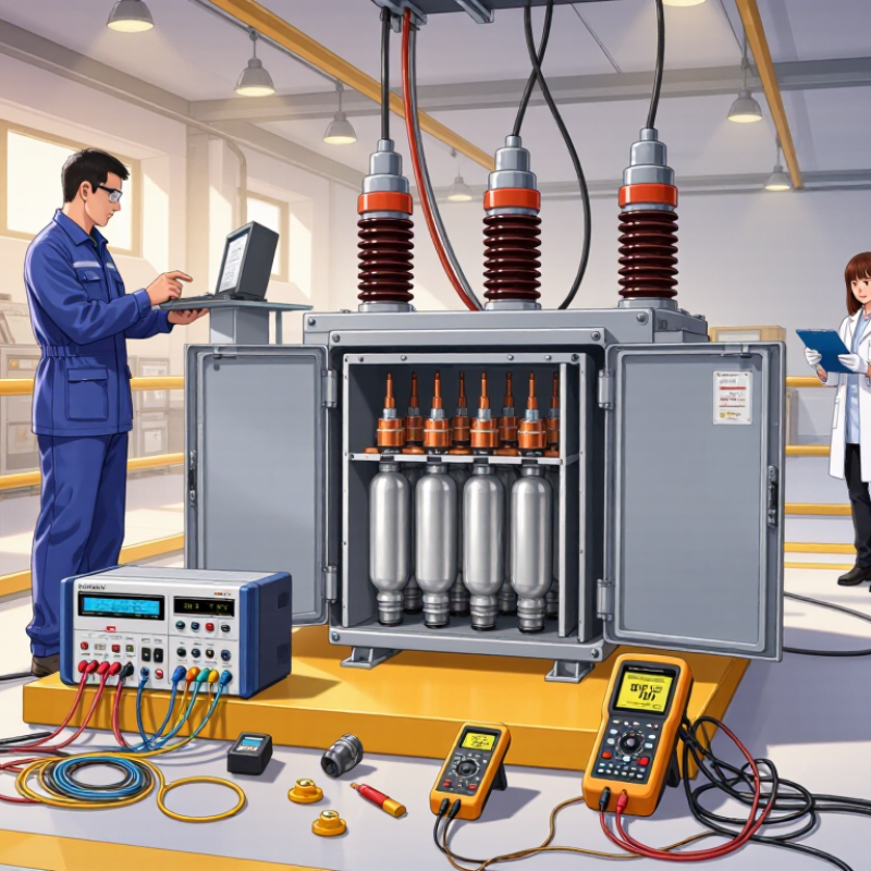
What Is a VCB Test and Why Is It Important?
A VCB, or vacuum circuit breaker, test checks whether a breaker can interrupt electrical current safely. It is important because the breaker protects equipment during faults, overloads, and short circuits. Inside the interrupter, vacuum helps extinguish the arc when contacts separate. If that vacuum weakens, interruption may become unreliable. A hidden defect can damage cables, transformers, or connected machinery.
Safety comes first. The circuit is isolated, locked out, and verified as de-energized by qualified personnel. Technicians then inspect the breaker for cracks, contamination, loose connections, and unusual wear. They measure insulation resistance and contact resistance with calibrated instruments. A vacuum integrity test checks for leakage or reduced insulating strength. Timing tests record how quickly the contacts open and close. Mechanical operations may also be repeated to reveal sticking or uneven movement.
Test results should be compared with applicable standards, service records, and the equipment manufacturer’s limits. Small changes can matter. A low resistance reading may indicate contact damage, while slow operation can suggest mechanical wear. No test is perfect. A passing result does not guarantee future performance under every fault condition. Temperature, instrument accuracy, and testing technique can affect the findings. Clear records, careful judgment, and periodic retesting provide a more reliable view of the breaker’s condition.
What Is a VCB Test and How Is It Performed? - What Is a VCB Test and Why Is It Important?
| Test Dimension | What It Checks | Typical Test Method | Common Reference or Acceptance Guidance | Why It Matters |
|---|---|---|---|---|
| Insulation Resistance | Detects moisture, contamination, aging, or damage in the primary circuit and insulation system. | Apply a suitable DC insulation-resistance voltage between phases, phase-to-ground, and across open contacts using an insulation tester. | Results should be stable and consistent with the equipment rating, manufacturer instructions, temperature, and applicable standards. Compare with previous test records. | Low or declining insulation resistance can indicate a developing insulation failure or increased flashover risk. |
| Contact Resistance | Measures resistance through the closed main contacts and current path. | Inject a stable high test current, commonly 100 A or higher, and measure the voltage drop across each pole with a micro-ohmmeter. | Readings are normally expected to be in the micro-ohm range and reasonably balanced between poles. The equipment documentation and applicable standard govern the limit. | Excessive or unbalanced resistance may cause overheating, energy losses, and premature contact wear. |
| Vacuum Integrity | Verifies that the vacuum interrupter has sufficient vacuum insulation and no loss of vacuum. | Perform a vacuum bottle withstand or vacuum integrity test with an approved AC or DC test set, following the interrupter manufacturer’s procedure. | The test voltage and duration depend on the interrupter design and rated voltage. The interrupter should withstand the specified test without breakdown or abnormal leakage. | A failed vacuum interrupter can no longer safely interrupt fault current or provide adequate isolation. |
| Power-Frequency Withstand | Checks the dielectric strength of the breaker insulation under an elevated power-frequency voltage. | Apply the prescribed test voltage between phases, from each phase to ground, and across open contacts where required. | The voltage level and duration are selected according to the breaker’s rated insulation level and the applicable testing standard. No flashover or disruptive discharge should occur. | Confirms that clearances and insulation can withstand temporary overvoltage conditions. |
| Opening and Closing Time | Measures operating speed, pole simultaneity, and the timing of auxiliary contacts. | Connect a circuit-breaker analyzer to the main and auxiliary contacts, then record several open, close, and trip operations. | Typical medium-voltage VCB operating times are often measured in tens of milliseconds, but acceptable values vary by design. Pole-to-pole timing should remain within the specified tolerance. | Incorrect timing can cause excessive switching stress, phase imbalance, or failure of protection schemes. |
| Trip and Close Coil Test | Checks the electrical operation of the trip coil, closing coil, control circuit, and associated wiring. | Verify coil resistance, apply the rated control voltage, and confirm reliable opening and closing through local and remote commands where applicable. | Coil resistance should be consistent with the equipment documentation, and the mechanism should operate reliably at the specified control voltage. | Identifies weak coils, loose connections, incorrect control voltage, or control-circuit failures. |
| Mechanical Operation | Evaluates the operating mechanism, charging motor, springs, linkages, lubrication, and wear. | Operate the breaker repeatedly in open, close, and trip sequences while observing abnormal noise, sluggish movement, incomplete charging, or failure to latch. | The breaker should complete the required operating sequence without sticking, excessive vibration, or abnormal mechanical noise. | Mechanical defects can prevent the breaker from interrupting a fault or closing when required. |
| Interlock and Functional Test | Confirms correct operation of electrical interlocks, racking mechanisms, position indicators, anti-pumping circuits, and protection interfaces. | Test the breaker in the service, test, and disconnected positions, and verify that prohibited operations are blocked. | Every safety interlock and indication should operate according to the approved control schematic and operating procedure. | Prevents unsafe switching, incorrect isolation, equipment damage, and operator exposure. |
| Test Documentation | Records test conditions, measured values, instrument details, and final assessment. | Document the breaker identification, ambient temperature, test equipment calibration status, test sequence, results, defects, and corrective actions. | Results should be compared with commissioning data, previous maintenance records, equipment instructions, and applicable standards. | Trend analysis helps identify deterioration before it develops into an operational failure. |
Safety note: VCB testing involves hazardous electrical energy. Testing should be performed only by qualified personnel using approved procedures, suitable personal protective equipment, isolation controls, and calibrated instruments. Exact test voltages, durations, resistance limits, and timing tolerances must be taken from the applicable standard and the circuit breaker’s technical documentation.